Gear Geometry
For the Gleason Spiral Metric System f.e., the geometry is defined by a standardised theoretical basic rack profile and 8 independent
geometric quantities:
|
1 |
Outer transverse module |
met |
|
2 |
Number of teeth of pinion |
z1 |
|
3 |
Number of teeth of gear |
z2 |
|
4 |
Face width gear |
b2 |
|
5 |
Mean spiral angle gear |
βm2 |
|
6 |
Pinion profile shift coefficient |
xh1 |
|
7 |
Pinion thickness modification coefficient |
xs1 |
|
8 |
Shaft angle |
Σ |
The input is to be done with following dialog box:
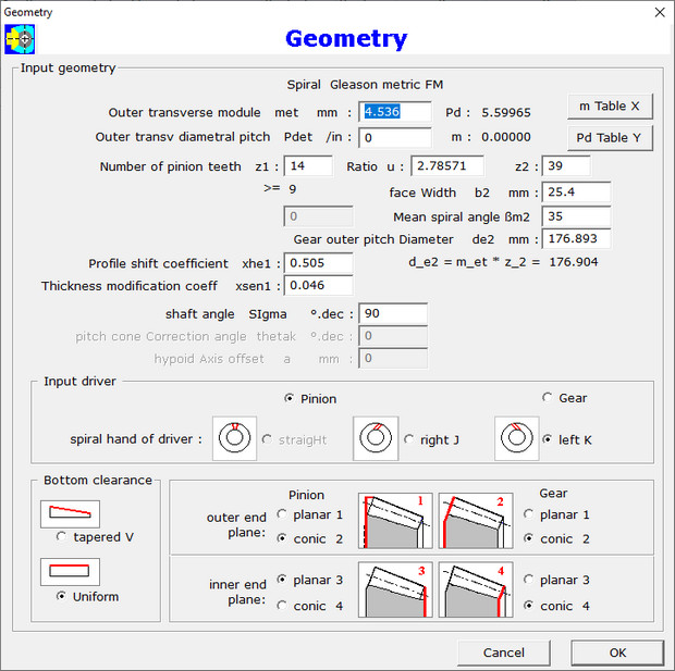
Input of gear outer pitch diameter de2 is also requested as a dependent parameter
de2 = met z2. Common practice is to round this outer pitch diameter while the spiral angle is
slightly adapted. In the Gleason Metric System, profile height shift modification is applied to avoid root undercutting if number of
teeth is less tthan 17 and thickness modification is applied to strengthen pinion teeth. In the Pd System the tooth proportions
are determined width equations containing factors which are derived from tables.
Input of spiral hand, selection of uniform bottom clearance and the limiting back and front planes for teeth are selected with radio
buttons.
Input of face mill cutter radius rc0 which is to derive from a list in a dialog box for management of face mill tools.
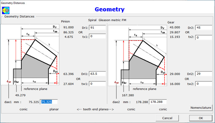
A list with standard Gleason face mill tools is supplied in a csv-file format with the program. Input of distances from crossing point is done
as shown in next dialog:
Calculation result is shown in next figure:
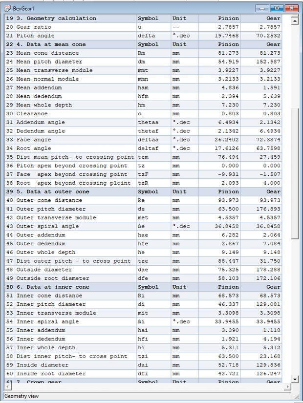
The calculation report can be exported in a .txt - or a .html file. The html file can be viewed with a browser.
Click here to open a Calculation Report Geometry in
a new blank page.
Go to the next web page to look for the gear forces.