CylGear
Application for calculation of Cylindrical Involute Gears
CylGear calculates
- executable gear domain and its boundary lines
- dimensioning of a gear pair
- gear geometry according to standard DIN 3960
- gear measurements: chordal thickness, span width and dimension over pins or balls
- contact path and diameters of profile points needed for profile grinding with profile correction
- the tooth forces in mesh point and the reaction forces in the bearings
- determination of the dynamic model
- load capacity according to standard ISO 6336
- dimensioning and verification of geometry and calculation of load capacity of a planetary gear train
Topics covered in this site
User Interface
CylGear is an application running under Microsoft Windows operating system.
The user can select a language for the user interface and output among:
- Dutch
- English
- French
- German
The user interface is very user friendly: the application guides the user through each calculation sequence.
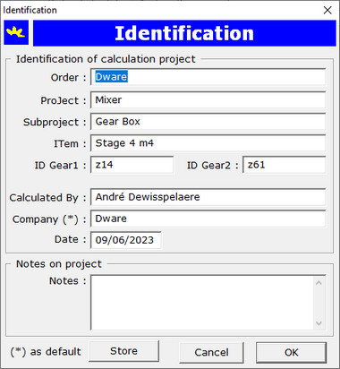
Identification of a Calculation Project
At the start of a new calculation project, a dialog box opens for input of data for the identification of the calculation project.
Gear Definition
A gear pair is defined by a standard theoretical basic rack and by seven independent geometrical parameters. The calculation
is being done for a gear1 and gear2 pair.
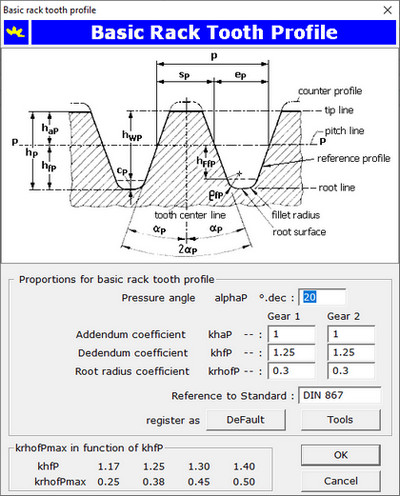
Theoretical Basic Rack
The theoretical basic rack is defined by the following proportions:
| |
pressure angle |
αP |
20.00 ° |
|
addendum coefficient |
khaP |
1.00 |
|
dedendum coefficient |
khfP |
1.25 |
|
tooth-root radius coefficient |
kρfP |
0.30 |
The proportions can be changed, input is to do with following dialog:
The basic rack proportions are stored as default values in the registry with a simple
mouse click on the command button Default.
The basic gear rules, the theoretical basic rack and two coefficients for the minimal normal crest width for external gear,
respectively minimal normal root space width for internal gear, are defining the executable gear domain. The application
calculates the boundary lines. Required input are the following proportions:
| External gear |
Gear boundary line G1 |
ksan |
0.20 |
| Internal gear |
Gear boundary line G5 |
kefn |
0.20 |
This two proportions are stored in the system registry and are used as default values for a next calculation.
The boundary lines are calculated for the given basic rack data as pressure angle αP, addendum and
dedendum coefficients. The boundary lines enclosing the executable gear domain are drawn in red color in the diagram in the dialog below:
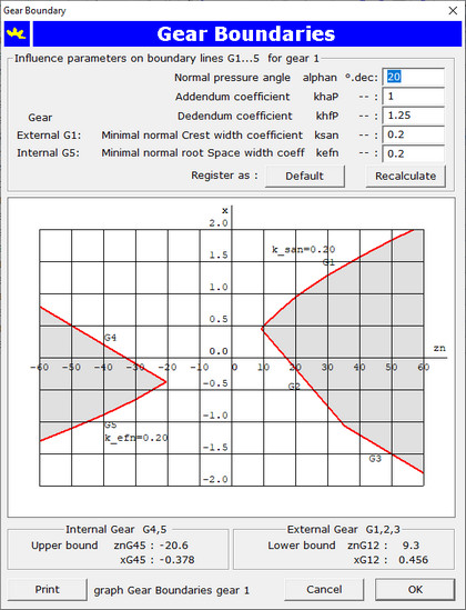
The gear boundary diagram can be printed on paper by a click with the mouse on the command button Print.
For a pressure angle 20 ° and a virtual number of teeth in normal section one should particularly in the range zn = 9 ... 60 teeth
pay attention to respect the gear boundary lines. That's exactly what the application is doing for you:
if a gear boundary condition is not satisfied a message box will warn you.
Definition of gear boundary lines:
External gear:
| |
Boundary line G1 |
xG1 |
maximum profile shift coefficient applicable from the condition to respect a minimum normal crest width of
san = ksan mn
|
| Boundary line G2 |
xG2 |
minimum profile shift coefficient to apply in order to avoid undercutting of the tooth-root |
| Boundary line G3 |
xG3 |
minimum profile shift coefficient to apply from the condition da >= db + 2 mn |
Internal gear:
| |
Boundary line G4 |
xG4 |
maximum profile shift coefficient to apply from the condition da <= db |
| Boundary line G5 |
xG5 |
minimum profile shift coefficient from the condition minimum normal tooth-root space width
efn = kefn mn |