Gear Geometry
The gear geometry is defined by a standardised theoretical basic rack profile and 7 independent geometrical quantities:
|
1 |
Center distance |
a |
|
2 |
Face width |
b |
|
3 |
Helix angle |
β |
|
4 |
Normal module |
mn |
|
5 |
Number of teeth of gear1 |
z1 |
|
6 |
Number of teeth of gear2 |
z2 |
|
7 |
One of both profile shift coefficients |
x1, x2 |
Input of obligatory and/or optional part of gear parameters with following dialog box:
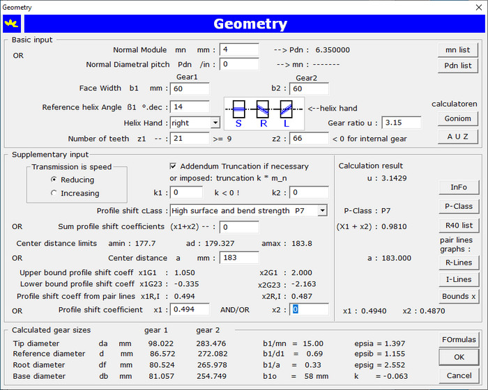
Edit or modification of one gear parameter followed by a press on the Tab key triggers a calculation: the user sees immediately
the effect of the latest input.
Note that the smallest allowable number of teeth for gear1 is displayed immediately behind the edit control for input
of number of teeth for gear1 z1. In this calculation, the helix angle β is token into account as you will
have noticed that it's input is preceding in the Tab order. Displayed are also: the reference center distance ad,
the limits for center distance amin,max, the upper and lower limits for the profile shift coefficients,
the optimum profile shift coefficients determined with the pair lines for reducing (R-lines) or
speed increasing (I-lines). The profile shift class corresponding with the sum of profile shift coefficients is displayed
in the list box.
With this dialog box, the user already has an idea about the size of the gear pair. On closing the dialog box all calculation
results are displayed in table form on the output window:
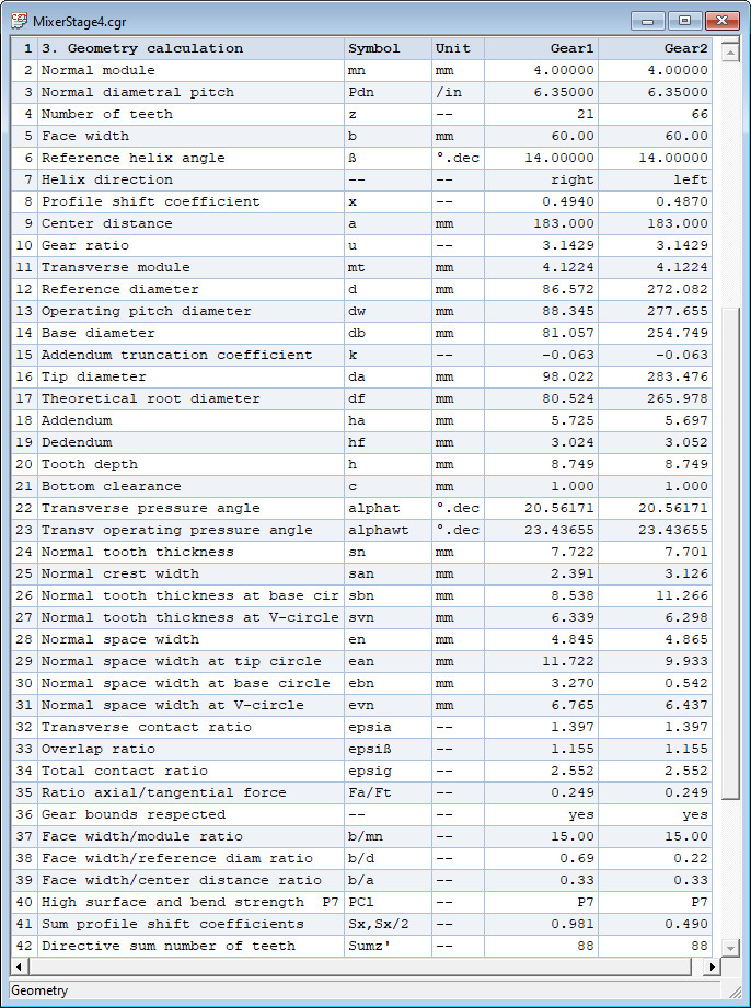
With a mouse click on a menu item, the results of the calculation can be exported in a text - or a html file.
Click here to open Calculation Report Geometry in a blank target page.
Go to next page for gear measurements.