Gear Load
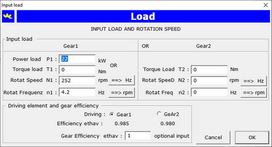
Input of gear load with one of following combination:
| |
Power on gear1 |
P1 |
kW |
and |
rotational frequency of gear1 |
n1 |
Hz |
| |
Torque on gear1 |
T1 |
Nm |
and |
rotational frequency of gear1 |
n1 |
Hz |
| |
Torque on gear2 |
T2 |
Nm |
and |
rotational frequency of gear2 |
n2 |
Hz |
Input is to do with dialog underneath:
Materials for Gears
The application provides a dialog box for the management of materials for gears. According the standard ISO 6336-5
the contact stress limit and bending stress limit are to determine in function of the tooth flank surface hardness using the
equation of straight line σH,F = Ax + B where x stands for the flank hardness, A is the slope coefficient and B
is the segment on y-axis. This three parameters are token from the standard. Input for a gear pair requires input of material
separately for gear1 and gear2, the material quality grade and the surface hardness of tooth flank. With the equation of the straight line
the contact stress limit value σHlim and the bending stress limit value σFlim
are determined in function of the surface hardness of tooth flank.
Gear Forces
Input of the coordinates of gear bearing points A and B and mesh point X. A cylindrical coordinate system is therefor being used.
The application calculates the gear forces: tangential transverse force Ft, radial transverse force Fr
and the axial force Fa. The reaction forces in the bearing points are also calculated.
Dynamic Model
The application provides for a powerfull modeller for the calculation of polar mass inertia moments for gear1 and gear2 even in the
dimensioning stage.
The mass of a third gear3 such as an intermediate gear or as a gear rigidly connected to a gear1 shaft can be taken into account.
The polar mass inertia moments are reduced to a single mass per unit of face width acting along the contact line.
The spring constant is determined with the single pair stiffness c' and the mean mesh stiffness per unit face width
cγ as described in the standard ISO 6336-1. The application calculates the natural frequency of
the mass-spring system and determines to which domain the speed of the gear pair wil belong. If the speed is in the critical domain,
the application will indicate which precautions can be taken to remediate for the problem.
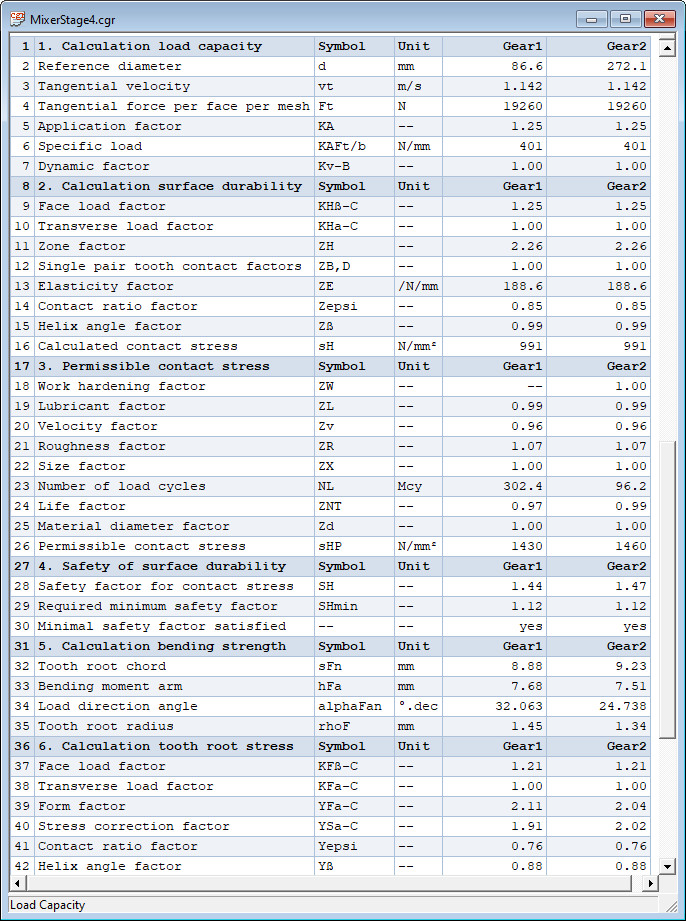
Load Capacity according standard ISO 6336-2,3
The application determines the influence factors, the contact - and bending stresses, the permissible stresses for contact
and root stress for the choosen gear materials. The safety factors for contact stress SH1,2 and
tooth root bending stress SF1,2 are calculated and compared with the respectively imposed minimum values.
The application warns with a messagebox if the imposed minimum safety factors are not satisfied.
See for a part of the output window below:
Output as text - or HTML file
The load capacity calculation report can be exported in a text (.txt) or HTML (.htm)
file with a simple mouse click on a menu item. This files can be opened by a text editor, respectively with a browser.
Click here on Calculation Report Load Capacity to open a complete
load capacity calculation report in a target blank page.
Are you already convinced that CylGear is a usefull calculation tool?
Navigate to the Contact Page and ask a quotation or further information about the application.
Go to the next web page to read about the dimensioning problem and the verification calculation of a planetary gear train.