Shaft Profile
The shaft profile is to define with form elements as cylinders and truncated cones.
Input with next dialog box:
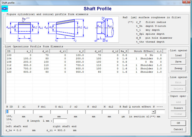
The location of each form element is defined by it's begin end end section:
|
begin coordinate z1 |
outside diameter do1 |
inside diameter di1 |
|
end coordinate z2 |
outside diameter do2 |
inside diameter di2 |
Input of shaft surface roughness RaS, rounding radius rF in section changes. A notch effect is
to locate in the begin section of a form element for shoulder in change of section, a U-notch, a flat of taper key way, a spline,
a pin hole, a thread, a shrink fit, case hardened, inductive or flame hardened.
The application calculates the weight and location of centroid for each form element. The total weight, the location of
centroid and the polar inertia moment Jz of shaft are calculated.
Concentrated masses
Concentrated masses fixed to the shaft are to be input with a special dialog box. This masses are converted into forces and added to the
load list if the option include in load list is checked off. This separate input is required to calculate the critical speed for bending
and torsion.
Go to next web page for examples of moments -, stress - and deflection diagrams.