Gear Measurement
Calculation of the diameter of measuring pins dM for the worm and the diameter of measuring balls dB
for wormwheel. Input of rounded values for this diameters, but they have to be as close as possible to the calculated values.
The application calculates: mean normal chordal thickness with tolerance in ± notation, diametral dimension over three pins Md1
for the worm, diametral dimension over two balls Md2 for wormwheel with respective tolerance. The backlash to be
expected is also calculated. The user can compose a measuremnt sheet by selection of options with check boxes. A composition can
be stored as default for the next calculations.
Materials for worm and wormwheels
The application provides a dialog box for management of materials for gears. According the standard ISO 6336-5
the endurance contact stress values and endurance bending stress values can be determined in function of the tooth flank hardness using an
equation of straight line σH,F = Ax + B where x stands for the flank hardness, A for the slope coefficient and B
for the segment on the y-axis. The data for wormwheel materials are derived from the text book Niemann-Winter Maschinenelemente Band III.
Input for a worm gear pair requires input of material separately for worm and wormwheel, the material quality grade and the hardness of tooth flank.
With the equation of the straight line the endurance contact stress value σHlim and the endurance bending stress
value σFlim are determined in function of the tooth flank hardness.
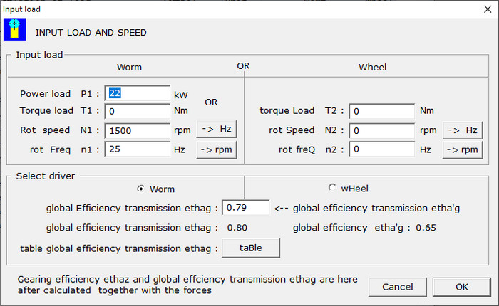
Load
Input of the load can be done with one of the following combinations:
| |
Power on worm |
P1 |
kW |
and |
rotational frequency worm |
n1 |
Hz |
| |
Torque on worm |
T1 |
Nm |
and |
rotational frequency worm |
n1 |
Hz |
| |
Torque on wheel |
T2 |
Nm |
and |
rotational frequency wormwheel |
n2 |
Hz |
Input with dialog:
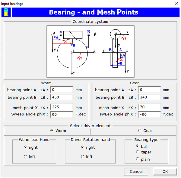
Bearing Points
Input of location of bearing points A and B and mesh point X with cylindrical coordinates as presented in
following dialog box:
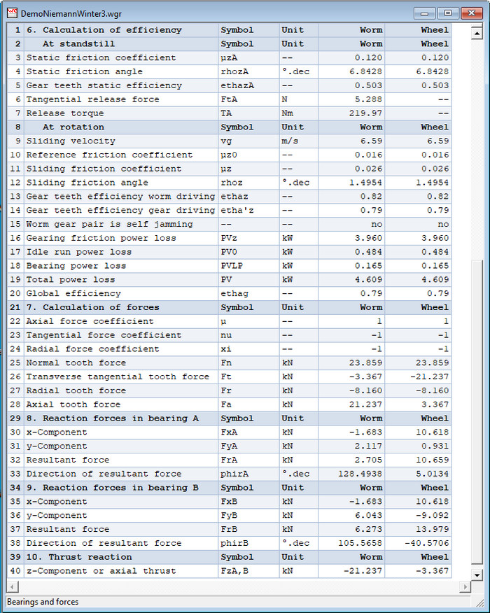
Worm Gear Forces
Calculation of transverse tangential force Ft, the radial force Fr and the axial force
Fa in the mesh point X and the reaction forces in the bearings A and B. The application checks if transmission is
self locking.
Calculation results are displayed on screen in a table as shown in following window:
The calculation results may also be exported in a .txt- or a .html-file. To have a look on a complete
forces calculation report, click on Calculation Report Forces to open
it in a blank page.
Go to next web page for load carrying capacity.